ABSTRACT
This project is a standalone automation of
unmanned railway gate control system using atmega microcontroller. Use of
embedded technology makes this closed loop feedback control system efficient
and reliable.Microcontroller allows dynamic and faster control.
The main aim of this project is to
automize the unmanned railway gate i.e. the gate is closed automatically
whenever the train comes and is opened after the train leaves the railway-road
crossing. Using this project, the arrival of the train can be identified in
either direction. For this purpose, two IR transmitter and receiver pairs are
used in this project.One IR TX-RX pair is placed at one end of the railway gate
and the second pair is placed at another end of the gate. Red led is used to
represent the closing of the gate and green colour led is used to represent the
opening of the gate. These are used for indication purpose.
Whenever any train is coming on the
track, the IR signal will be disturbed due to the interruption of the train.
Thus the microcontroller identifies the arrival of the train. Before closing
the gate, the microcontroller activates the buzzer to alert the people who are
on the track.The microcontroller then closes the gate by rotating the dc motor.
The microcontroller should know whether the train left the crossing or not to
open the gate. For this purpose, the second IR pair is used. This IR pair
identifies the train since the IR signal is interrupted when the train comes in
between the TX and RX. The micro controller will wait for the last compartment
to leave the IR pair and after leaving, the receiver again gets IR signal. Till
this time the gate is closed. Now, after the train had left the crossing, the microcontroller
will open the gate by rotating the dc motor.
CHAPTER 1
INTRODUCTION TO EMBEDDED SYSTEMS
An embedded system can be defined as a
computing device that does a specific focused job. Appliances such as the
air-conditioner, VCD player, DVD player, printer, fax machine, mobile phone
etc. are examples of embedded systems. Each of these appliances will have a
processor and special hardware to meet the specific requirement of the application
along with the embedded software that is executed by the processor for meeting
that specific requirement. The embedded software is also called “firmware”. The
desktop/laptop computer is a general purpose computer, you can use it for a
variety of applications such as playing games, word processing,
accounting, software development and so on.
Embedded
systems do a very specific task, they cannot be programmed to do different
things. Embedded systems have very limited resources, particularly the memory.
Generally, they do not have secondary storage devices such as the CDROM or the
floppy disk. Embedded systems have to work against some deadlines. A specific
job has to be completed within a specific time. In some embedded systems,
called real-time systems, the deadlines are stringent. Missing a deadline may
cause a catastrophe-loss of life or damage to property. Embedded systems are
constrained for power. As many embedded systems operate through a battery, the
power consumption has to be very low.
APPLICATION AREAS
Nearly
99 per cent of the processors manufactured end up in embedded systems. The
embedded system market is one of the highest growth areas as these systems are
used in very market segment - consumer appliances, office automation, industrial
automation, medical electronics, security, computer networking,
telecommunications, wireless technologies and so on.
Consumer
appliances:
At home we use a number of embedded systems which include digital camera,
digital diary, DVD player, electronic toys, microwave oven, remote controls for
TV and air-conditioner, VCO player, video game consoles, video recorders etc.
Today’s high-tech car has about 20 embedded systems for transmission control,
engine spark control, air-conditioning, navigation etc. Even wristwatches are
now becoming embedded systems. The palmtops are powerful embedded systems using
which we can carry out many general-purpose tasks such as playing games and
word processing.
Office
automation: The
office automation products using em embedded systems are copying machine, fax
machine, key telephone, modem, printer, scanner etc.
Industrial
automation:
Today a lot of industries use embedded systems for process control. These
include pharmaceutical, cement, sugar, oil exploration, nuclear energy,
electricity generation and transmission. The embedded systems for industrial
use are designed to carry out specific tasks such as monitoring the
temperature, pressure, humidity, voltage, current etc., and then take
appropriate action based on the monitored levels to control other devices or to
send information to a centralized monitoring station. In hazardous industrial
environment, where human presence has to be avoided, robots are used, which are
programmed to do specific jobs. The robots are now becoming very powerful and
carry out many interesting and complicated tasks such as hardware assembly.
Medical
electronics:
Almost every medical equipment in the hospital is an embedded system. These
equipments include diagnostic aids such as ECG, EEG, blood pressure measuring
devices, X-ray scanners; equipment used in blood analysis, radiation,
colonscopy, endoscopy etc. Developments in medical electronics have paved way
for more accurate diagnosis of diseases.
Security: Security of persons
and information has always been a major issue. We need to protect our homes and
offices; and also the information we transmit and store. Developing embedded
systems for security applications is one of the most lucrative businesses
nowadays. Security devices at homes, offices, airports etc. for authentication
and verification are embedded systems.
Computer
networks:
Computer network products such as bridges, routers, Integrated Services Digital
Networks (ISDN), Asynchronous Transfer Mode (ATM), X.25 and frame relay switches
are embedded systems which implement the necessary data communication
protocols. For example, a router interconnects two networks. The two networks
may be running different protocol stacks. Most networking equipments, other
than the end systems (desktop computers) we use to access the networks, are
embedded systems.
Telecommunications:
In the field of telecommunications, the embedded systems can be categorized as
subscriber terminals and network equipment. The subscriber terminals such as
key telephones, ISDN phones, terminal adapters, web cameras are embedded
systems. The network equipment includes multiplexers, multiple access systems,
Packet Assemblers Dissemblers (PADs), sate11ite modems etc. IP phone, IP
gateway, IP gatekeeper etc. are the latest embedded systems that provide very
low-cost voice communication over the Internet.
Wireless
technologies:
Advances in mobile communications are paving way for many interesting
applications using embedded systems. The mobile phone is one of the marvels of
the last decade of the 20th century. It is a very powerful embedded system that
provides voice communication while we are on the move. The Personal Digital
Assistants and the palmtops can now be used to access multimedia services
over the Internet. Mobile communication
infrastructure such as base station controllers, mobile switching centers are
also powerful embedded systems.
OVERVIEW OF
EMBEDDED SYSTEM ARCHITECTURE
Every
embedded system consists of custom-built hardware built around a Central
Processing Unit (CPU). This hardware also contains memory chips onto which the
software is loaded. The software residing on the memory chip is also called the
‘firmware’. The embedded system architecture can be represented as a layered
architecture as shown in Fig.

Fig:1.1
Embedded System Architecture
The operating system runs above the hardware,
and the application software runs above the operating system. The same
architecture is applicable to any computer including a desktop computer.
However, there are significant differences. It is not compulsory to have an
operating system in every embedded system. For small appliances such as remote
control units, air conditioners, toys etc., there is no need for an
operating system and you can write only the software specific to that
application. For applications involving complex processing, it is advisable to
have an operating system. In such a case, you need to integrate the application
software with the operating system and then transfer the entire software on to
the memory chip. Once the software is transferred to the memory chip, the
software will continue to run for a long time you don’t need to reload
new software.
Now,
let us see the details of the various building blocks of the hardware of an
embedded system.
Central
Processing Unit (CPU): The
Central Processing Unit can be any of the following: microcontroller,
microprocessor or Digital Signal Processor (DSP). A micro-controller is a
low-cost processor. Its main attraction is that on the chip itself, there will
be many other components such as memory, serial communication interface, analog-to
digital converter etc. On the other hand, microprocessors are more powerful,
but you need to use many external components with them. DSP is used mainly for
applications in which signal processing is involved such as audio and video
processing.
Memory: The
memory is categorized as Random Access 11emory (RAM) and Read Only Memory
(ROM). The contents of the RAM will be erased if power is switched off to the
chip, whereas ROM retains the contents even if the power is switched off. So,
the firmware is stored in the ROM. When power is switched on, the processor
reads the ROM; the program is program is executed.
Input
devices: Unlike
the desktops, the input devices to an embedded system have very limited
capability. There will be no keyboard or a mouse, and hence interacting with
the embedded system is no easy task. Many embedded systems will have a small
keypad-you press one key to give a specific command. A keypad may be used to
input only the digits. Many embedded systems used in process control do not
have any input device for user interaction; they take inputs from sensors
or transducers 1’fnd produce electrical signals that are in turn fed to other
systems.
Output
devices: The
output devices of the embedded systems also have very limited capability. Some
embedded systems will have a few Light Emitting Diodes (LEDs) to indicate
the health status of the system modules, or for visual indication of
alarms. A small Liquid Crystal Display (LCD) may also be used to display some
important parameters.
Communication
interfaces: The
embedded systems may need to, interact with other embedded systems at they may
have to transmit data to a desktop. To facilitate this, the embedded systems
are provided with one or a few communication interfaces such as RS232,
RS422, RS485, Universal Serial Bus (USB), IEEE 1394, Ethernet etc.
Application
specific circuitry: Sensors,
transducers, special processing and control circuitry may be required fat an
embedded system, depending on its application. This circuitry interacts with
the processor to carry out the necessary work. The entire hardware has to be
given power supply either through the 230 volts main supply or through a
battery. The hardware has to design in such a way that the power consumption is
minimized.
CHAPTER 2
OVERVIEW OF PROJECT
2.1 INTRODUCTION
The railway system is the most commonly
used transportation mode in India. It is also one of those modes of transport
that faces a lot of challenges due to human errors such as level cross
accidents, collisions, etc. A level cross, an intersection of a road and a
railway line, requires human coordination, the lack of which leads to
accidents.Level crosses are controlled by manually operated gates. In order to
avoid the human errors that could occur during the operation of gates,the
concept of sensor based railway gate ontroller is introduced.
Level crossings are managed by the gatekeeper
and the gatekeeper is instructed by the means of telephone at most of the level
cross from the control room. But the rate of manual error that could occur at
these level crosses are high because they are unsafe to perform without actual
knowledge about the train time table. Delay in the opening and closing of the
gate could lead to railway accidents. The present work attempts to develop a
system which automates gate operations (opening and closing) at the level cross
using arduino micro-controller.
The major challenge faced by the
Indian railway system is the increasing accident rate at the level crosses. The
existing system involves the manual gate operation by the gate keepers based on
the signals received from the control room. The human errors such as delay in
informing the gatekeeper about the arrival of the train, delay in the gate
operation by the gate keeper, obstacle stuck in the level cross etc. leads to
the increasing rate of accidents at the level cross.
Thus the sensor based railway gate
controller system aims to deal with two things. It reduces the total time taken
for the gate operation at the level cross and also ensures the safety of the
passengers at the level cross during when the train passes. The reduction in
the direct human intervention during the gate operation in turn helps to reduce
the collision and accidents at the level cross. Since the gate operations are
automated based on the sensors, the time for which the gate is closed is
less.The main aim of the project is thus intends to develop an automatic
railway gate control system which is reliable and secured than the existing
manual systems.
2.2
SYSTEM ARCHITECTURE :
Sensor based railway gate
automation system is developed to automate the process of opening and closing
of gate at the railway level crosses. The system detects the arrival and the
departure of train for the gate operation using different types of sensors. The
proposed system uses two infrared sensor sets to identify the arrival and
departure of trains.
In India the maximum speed at which a train moves is
91.82km/hr and the minimum speed of a passenger/goods train is 59km/hr. Hence
the ideal distance at which the sensors could be placed to detect the arrival
of the train is 2 km from the level cross and the departure of the train is 1km
and thus the gate will not be closed for more than 5 minutes.In real time, the IR Sensor sets are
placed on the track at a distance of 2km and 1km on both sides of the level
crossing.The system also uses DC motors to control the operation of the gates.
The buzzer is used to indicate the arrival of the train within a stipulated
time.
IR sensor set 1 detects the
arrival of a train. Once it detects a train, it sends a signal to buzzer to
indicate the arrival of train and red LEDs are switched on for the traffic to
know the arrival of the train. , DC motors are powered on. The DC motors starts
and the gates begin to close.The train then travels to IR sensor set 2. After
the train passes the gates and nears IR Sensor set 2, a signal is again sent to
the DC motors and the gates open and green LEDs are switched on for the road
traffic to pass.
2.3 BLOCK DIAGRAM:

CHAPTER 3
HARDWARE
IMPLEMENTATION OF THE PROJECT
This
chapter briefly explains about the Hardware Implementation of the project. It discusses
the design and its working with the help of block diagram in detail. It
explains the features, timer programming, serial communication, interrupts of
ATMEGA328. It also explains the various modules used in this project.
PROJECT
DESIGN
The implementation of the project design can be divided in two
parts.
● Hardware implementation
● Firmware implementation
Hardware implementation deals in drawing the schematic on the
plane paper according to the application, testing the schematic design over the
breadboard using the various IC’s to find if the design meets the objective,
carrying out the PCB layout of the schematic tested on breadboard, finally
preparing the board and testing the designed hardware.
The firmware part deals in programming the microcontroller so that
it can control the operation of the IC’s used in the implementation. In the
present work, we have used the Proteus design software for PCB circuit design,
the ARDUINO software development tool to write and compile the source code, which
has been written in the C language. The firmware implementation is explained in
the next chapter.
The block diagram of the design shown
in fig 2.1 consists of power supply unit, microcontroller, DC motor. The brief
description of each unit is explained as follows.
BLOCK DIAGRAM:

3.1 Power Supply:
The
input to the circuit is applied from the regulated power supply. The a.c. input
i.e., 230V from the mains supply is step down by the transformer to 12V and is
fed to a rectifier. The output obtained from the rectifier is a pulsating d.c
voltage. So in order to get a pure d.c voltage, the output voltage from the
rectifier is fed to a filter to remove any a.c components present even after
rectification. Now, this voltage is given to a voltage regulator to obtain a
pure constant dc voltage.

Transformer:
Usually, DC voltages are required to
operate various electronic equipment and these voltages are 5V, 9V or 12V. But
these voltages cannot be obtained directly. Thus the a.c input available at the
mains supply i.e., 230V is to be brought down to the required voltage level.
This is done by a transformer. Thus, a step down transformer is employed to
decrease the voltage to a required level.
Rectifier: The
output from the transformer is fed to the rectifier. It converts A.C. into
pulsating D.C. The rectifier may be a half wave or a full wave rectifier. In
this project, a bridge rectifier is used because of its merits like good
stability and full wave rectification.
Filter: Capacitive
filter is used in this project. It removes the ripples from the output of
rectifier and smoothens the D.C. Output received from this filter is constant
until the mains voltage and load is maintained constant. However, if either of
the two is varied, D.C. voltage received at this point changes. Therefore a
regulator is applied at the output stage.
Voltage regulator: As
the name itself implies, it regulates the input applied to it. A voltage
regulator is an electrical regulator designed to automatically maintain a
constant voltage level. In this project, power supply of 5V and 12V are
required. In order to obtain these voltage levels, 7805 and 7812 voltage
regulators are to be used. The first number 78 represents positive supply and
the numbers 05, 12 represent the required output voltage levels.

3.2 ARDUINO
DEVELOPMENT BOARD:
The
Arduino Uno is a microcontroller board based on the ATmega328. It has 14
digital input/output pins (of which 6 can be used as PWM outputs), 6 analog
inputs, a 16 MHz ceramic resonator, a USB connection, a power jack, an ICSP
header, and a reset button. It contains everything needed to support the
microcontroller; simply connect it to a computer with a USB cable or power it
with a AC-to-DC adapter or battery to get started.
The
Uno differs from all preceding boards in that it does not use the FTDI
USB-to-serial driver chip. Instead, it features the Atmega16U2 (Atmega8U2 up to
version R2) programmed as a USB to- serial converter.
Revision3
of the board has the following new features:
1.0
pinout: added SDA and SCL pins that are near to the AREF pin and two other new
pins placed near to the RESET pin, the IOREF that allow the shields to adapt to
the voltage provided from the board. In future, shields will be compatible both
with the board that use the AVR, which operate with 5V and with the Arduino Due
that operate with 3.3V. The second one is a not connected pin, that is reserved
for future purposes.
Atmega
16U2 replace the 8U2.
"Uno"
means one in Italian and is named to mark the upcoming release of Arduino 1.0.
The Uno and version 1.0 will be the reference versions of Arduino, moving
forward. The Uno is the latest in a series of USB Arduino boards, and the
reference model for the Arduino platform; for a comparison with previous
version.
Ardunio Board:

The name says it all on this one. An
ATmega328 in DIP package, pre-loaded with the Arduino (16MHz) Bootloader. This
will allow you to use Arduino code in your custom embedded project without
having to use an actual Arduino board.
To
get this chip working with Arduino IDE, you will need an external 16MHz crystal
or resonator, a 5V supply, and a serial connection. If you are not comfortable
doing this, we recommend purchasing the Arduino Duemilanove board that has all
of these built into the board.
3.2.1.Pin diagram:


3.2.2.
Specifications
|
|
Microcontroller
|
ATmega328
|
Operating Voltage
|
5V
|
Input Voltage (recommended)
|
7 – 12V
|
Input Voltage (limits)
|
6 – 20V
|
Digital I/O Pins
|
14 (of which 6 provide PWM output)
|
Analog Input Pins
|
6
|
DC Current per I/O Pin
|
40mA
|
DC Current for 3.3V Pin
|
50mA
|
Flash Memory
|
32kB of which 0.5 KB used by boot loader
|
SRAM
|
2 KB (ATmega328)
|
EEPROM
|
1 KB (ATmega328)
|
Clock Speed
|
16 MHz
|
3.2.3.Power:
The
Arduino Uno can be powered via the USB connection or with an external power
supply. The power source is selected automatically. External (non-USB) power
can come either from an AC-to-DC adapter (wall-wart) or battery. The adapter
can be connected by plugging a 2.1mm center-positive plug into the board's
power jack. Leads from a battery can be inserted in the GND and VIN pin headers
of the POWER connector.
The
board can operate on an external supply of 6 to 20 volts. If supplied with less
than 7V, however, the 5V pin may supply less than five volts and the board may
be unstable. If using more than 12V, the voltage regulator may overheat and
damage the board. The recommended range is 7 to 12 volts. The power pins are as
follows:
VIN: The input voltage to
the Arduino board when it's using an external power source (as opposed to 5
volts from the USB connection or other regulated power source). You can supply
voltage through this pin, or if supplying voltage via the power jack, access it
through this pin.
5V:
This pin outputs a regulated 5V from
the regulator on the board. The board can be supplied with power either from
the DC power jack (7 - 12V), the USB connector (5V), or the VIN pin of the
board (7-12V). Supplying voltage via the 5V or 3.3V pins bypasses the
regulator, and can damage your board.
3V3:
A 3.3 volt supply generated by the on-board regulator. Maximum current draw is
50 mA.
GND: Ground pins.
IOREF: This pin on the
Arduino board provides the voltage reference with which the microcontroller
operates. A properly configured shield can read the IOREF pin voltage and select the appropriate power source or
enable voltage translators on the outputs for working with the 5V or 3.3V.
3.2.4.Input
and Outputs:
Each
of the 14 digital pins on the Uno can be used as an input or output, using
pinMode(), digitalWrite(), and digitalRead()functions. They operate at 5 volts.
Each pin can provide or receive a maximum of 40 mA and has an internal pull-up
resistor (disconnected by default) of 20-50 kOhms. In addition, some pins have
specialized functions:
Serial: 0 (RX) and 1 (TX). Used
to receive (RX) and transmit (TX) TTL serial data. These pins are connected to
the corresponding pins of the ATmega8U2 USB-to-TTL Serial chip.
External
Interrupts: 2 and
3. These pins can be configured to trigger an
interrupt on a low value, a rising or falling edge, or a change in value. See
the attachInterrupt() function for details.
PWM: 3, 5, 6, 9, 10, and 11. Provide
8-bit PWM output with the analogWrite() function.
SPI: 10 (SS), 11 (MOSI), 12 (MISO), 13 (SCK). These
pins support SPI communication using the SPI library.
LED: 13. There is a built-in
LED connected to digital pin 13. When the pin is HIGH value, the LED is on,
when the pin is LOW, it's off.
The
Uno has 6 analog inputs, labeled A0 through A5, each of which provide 10 bits
of resolution (i.e. 1024 different values). By default they measure from ground
to 5 volts, though is it possible to change the upper end of their range using
the AREF pin and the analogReference() function. Additionally, some pins have
specialized functionality:
TWI:
A4 or SDA
pin and A5 or SCL pin. Support TWI
communication using the Wire library.
There
are a couple of other pins on the board:
AREF: Reference voltage for
the analog inputs. Used with analogReference().
RESET: Bring this line LOW
to reset the microcontroller. Typically used to add a reset button to shields
which block the one on the board.
3.2.5.Communication:
The
Arduino Uno has a number of facilities for communicating with a computer,
another Arduino, or other microcontrollers. The ATmega328 provides UART TTL
(5V) serial communication, which is available on digital pins 0 (RX) and 1
(TX). An ATmega16U2 on the board channels this serial communication over USB
and appears as a virtual com port to software on the computer. The 16U2
firmware uses the standard USB COM drivers, and no external driver is needed.
However, on Windows, a .inf file is required. The Arduino software includes a
serial monitor which allows simple textual data to be sent to and from the
Arduino board. The RX and TX LEDs on the board will flash when data is being
transmitted via the USB-to-serial chip and USB connection to the computer (but
not for serial communication on pins 0 and 1).
A Software Serial library allows for
serial communication on any of the Uno's digital pins. The ATmega328 also
supports I2C (TWI) and SPI communication. The Arduino software includes a Wire
library to simplify use of the I2C bus; see the documentation for details. For
SPI communication, use the SPI library.
3.2.6.Programming:
The
Arduino Uno can be programmed with the Arduino software.
The
ATmega328 on the Arduino Uno comes preburned with a bootloader that allows you
to upload new code to it without the use of an external hardware programmer. It
communicates using the original STK500 protocol (reference, C headerfiles).
You
can also bypass the bootloader and program the microcontroller through the ICSP
(In- Circuit Serial Programming) header; see these instructions for details.
The
ATmega16U2 (or 8U2 in the rev1 and rev2 boards) firmware source code is
available. The ATmega16U2/8U2 is loaded with a DFU bootloader, which can be
activated by:
●
On Rev1 boards: connecting the solder jumper on the back of the board (near the
map of Italy) and then resetting the 8U2.
●
On Rev2 or later boards: there is a resistor that pulling the 8U2/16U2 HWB line
to ground, making it easier to put into DFU mode.
●
You can then use Atmel's FLIP software (Windows) or the DFU programmer (Mac OS
X and Linux) to load a new firmware. Or you can use the ISP header with an
external programmer (overwriting the DFU bootloader). See this user-contributed
tutorial for more information.
3.2.7.Automatic
(Software) Reset:
Rather than requiring a physical
press of the reset button before an upload, the Arduino Uno is designed in a
way that allows it to be reset by software running on a connected computer. One
of the hardware flow control lines (DTR) of theATmega8U2/16U2 is connected to
the reset line of the ATmega328 via a 100 nanofarad capacitor. When this line
is asserted (taken low), the reset line drops long enough to reset the chip.
The Arduino software uses this capability to allow you to upload code by simply
pressing the upload button in the Arduino environment. This means that the
bootloader can have a shorter timeout, as the lowering of DTR can be
well-coordinated with the start of the upload.
This
setup has other implications. When the Uno is connected to either a computer
running Mac OS X or Linux, it resets each time a connection is made to it from
software (via USB). For the following half-second or so, the bootloader is
running on the Uno. While it is programmed to ignore malformed data (i.e.
anything besides an upload of new code), it will intercept the first few bytes
of data sent to the board after a connection is opened. If a sketch running on
the board receives one-time configuration or other data when it first starts,
make sure that the software with which
it communicates waits a second after opening the connection and before sending
this data. The Uno contains a trace that can be cut to disable the auto-reset.
The pads on either side of the trace can be soldered together to re-enable it.
It's labeled "RESET-EN". You may also be able to disable the
auto-reset by connecting a 110 ohm resistor from 5V to the reset line.
3.2.8.USB
Overcurrent Protection:
The
Arduino Uno has a resettable polyfuse that protects your computer's USB ports
from shorts and overcurrent. Although most computers provide their own internal
protection, the fuse provides an extra layer of protection. If more than 500 mA
is applied to the USB port, the fuse will automatically break the connection until
the short or overload is removed.
3.2.9.Physical
Characteristics:
The
maximum length and width of the Uno PCB are 2.7 and 2.1 inches respectively,
with the USB connector and power jack extending beyond the former dimension.
Four screw holes allow the board to be attached to a surface or case. Note that
the distance between digital pins 7 and 8 is 160 mil (0.16"), not an even
multiple of the 100 mil spacing of the other pins.
3.3.PROXIMITY IR
SENSOR:
3.3.1 Introduction:
Proximity IR Sensor is
used to detect objects and obstacles in front of sensor. Sensor keeps
transmitting infrared light and when any object comes near, it is detected by
the sensor by monitoring the reflected light from the object.

3.3.2 Features
● IR transmitter LEDs
● 3 pin easy interface connector
● Indicator LED
● Up to 20cm range for white object
● Can differentiate between black and white colors
● Active High on object
detection
3.3.3 Specifications
● Power Supply : 5V DC Power Consumption: 50mA max
● Detection range 20 cm
● Operation range varies according to color of the
object, light color has more range.
● Detection Indicator LED
● Digital output. Active with logic “1”
● Dimensions : 41x27 mm
3.3.4 How to use
● To use sensor you only need power the sensor by
connect two wires +5V and GND to Pin’1’ & Pin’2’ respectively. Leave middle
output pin for interfacing with any controller.
●
When LED is off the output is Low.
●
Bring any object nearby the Sensor and the LED will lit up and output becomes
High.
●
The output is active High and can be given directly to microcontroller or using
current
limiting
1K resistor in series for interfacing applications.
●
When there is "NO OBJECT" or "DARK OBJECT" present, than
Transmitted IR will not reflect back to RX(Photo Diode) and Vout (Output) wil
be LOW.

●
When "LIGHT -COLOR OBJECT" is present, than Transmitted IR will
reflect back andVout (Output) will be HIGH.

3.3.5Interfacing:
Proximity IR Sensor Module & Microcontroller,
through which it is interface, should have common GND & VCC +5V. Current
limiting resistor of 220ohm to 1K can be used to connect Vout pin of Proximity IR Sensor Module with
any digital I/O pin of controller.

NOTE:
Please ensure polarity of power supply before connecting to module.
3.3.6 ELEMENTS OF INFRARED
DETECTION SYSTEM
A typical system for detecting
infrared radiation is given in the following block diagram :
 1.Infrared Source
All objects above 0 K radiate
infrared energy and hence are infrared sources. Infrared sources also include
blackbody radiators, tungsten lamps, silicon carbide, and various others. For
active IR sensors, infrared Lasers and LEDs of specific IR wavelengths are used
as IR sources.
2.Transmission Medium
Three main types of
transmission medium used for Infrared transmission are vacuum, the atmosphere,
and optical fibers.
The transmission of IR –
radiation is affected by presence of CO2, water vapour and other elements in
the atmosphere. Due to absorption by molecules of water carbon dioxide, ozone,
etc. the atmosphere highly attenuates most IR wavelengths leaving some
important IR windows in the electromagnetic spectrum; these are primarily
utilized by thermal imaging/ remote sensing applications.
• Medium wave IR
(MWIR:3-5 µm)
• Long wave IR
(LWIR:8-14 µm)
Choice of IR band or a specific
wavelength is dictated by the technical requirements of a specific application.
3. Optical
Components.
Often optical components are
required to converge or focus infrared radiations, to limit spectral response,
etc. To converge/focus radiations, optical lenses made of quartz, CaF2, Ge and
Si, polyethylene Fresnel lenses, and mirrors made of Al, Au or a similar
material are used. For limiting spectral responses, bandpass filters are
used. Choppers are used to pass/ interrupt the IR beams.
4.
Infrared detectors.
Various types of detectors are
used in IR sensors. Important specifications of detectors are
• Photosensitivity or Responsivity
Responsivity is the Output
Voltage/Current per watt of incident energy. Higher the better.
• Noise Equivalent Power (NEP)
NEP represents detection
ability of a detector and is the amount of incident light equal to intrinsic
noise level of a detector.
•Detectivity(D*: D-star)
D* is the photosensitivity per
unit area of a detector. It is a measure of S/N ratio of a detector. D* is
inversely proportional to NEP. Larger D* indicates better sensing element.
In addition, wavelength region or temperature
to be measured, response time, cooling mechanism, active area, no of elements,
package, linearity, stability, temperature characteristics, etc. are important
parameters which need attention while selecting IR detectors.
5.Signal
Processing
Since detector outputs are
typically very small, preamplifiers with associated circuitry are used to
further process the received signals.
3.4.DC MOTOR:
3.4.1. Introduction to DC motor:
Almost every mechanical movement that
we see around us is accomplished by an electric motor. Motors take electrical
energy and produce mechanical energy.
A direct current (DC) motor is a fairly simple electric motor that uses
electricity and a magnetic field to produce torque, which causes it to turn. At
its most simple, it requires two magnets of opposite polarity and an electric
coil, which acts as an electromagnet. The repellent and attractive
electromagnetic forces of the magnets provide the torque that causes the motor
to turn.

3.4.2 Construction
DC motors consist of one set of coils, called armature winding, inside
another set of coils or a set of permanent magnets, called the stator. Applying
a voltage to the coils produces a torque in the armature, resulting in motion.
Stator
·
The stator is the stationary outside part of a motor.
·
The stator of a permanent magnet dc motor is composed of two
or more permanent magnet pole pieces.
·
The magnetic field can alternatively be created by an electromagnet.
In this case, a DC coil (field
·
winding) is wound around a magnetic material that forms part
of the stator.
Rotor
·
The rotor is the inner part which rotates.
·
The rotor is composed of windings (called armature windings)
which are connected to the external
·
circuit through a mechanical commutator.
·
Both stator and rotor are made of ferromagnetic materials.
The two are separated by air-gap.
Winding
A winding is made up of series or
parallel connection of coils.
·
Armature winding - The winding through which the
voltage is applied or induced.
·
Field winding - The winding through which a current
is passed to produce flux (for the electromagnet)
·
Windings are usually made of copper.
3.4.3 Principle of operation
This DC or direct current motor works on the
principal, when a current carrying conductor is placed in a magnetic
field, it experiences a torque and has a tendency to move. This is known as
motoring action. If the direction of current in the wire is reversed, the direction of
rotation also reverses. When magnetic field and electric field interact they produce a
mechanical force, and based on that the working
principle of dc motor
established.

The direction
of rotation of a this motor is given by Fleming’s left hand rule, which states
that if the index finger, middle finger and thumb of your left hand are
extended mutually perpendicular to each other and if the index finger
represents the direction of magnetic field, middle finger indicates the direction of
current, then the thumb represents the direction in which force is experienced
by the shaft of the dc motor.
Structurally
and construction wise a direct current motor is exactly similar to a DC
generator, but
electrically it is just the opposite. Here we unlike a generator we supply
electrical energy to the input port and derive mechanical energy from the
output port.
3.4.4. Types of DC motors
1.
Shunt DC motor: The rotor and stator windings are
connected in parallel.
2.
Sparately Excited motor: The rotor and stator are each connected
from a different power supply, this gives another degree of freedom for
controlling the motor over the shunt.
3.
Series motor: the stator and rotor windings are connected in series. Thus
the torque is proportional to I2 so it gives the highest torque per current
ratio over all other dc motors. It is therefore used in starter motors of cars
and elevator motors.
4.
Permanent Magnet (PMDC) motors: The stator is a permanent magnet, so
the motor is smaller in size.
5.
Compouned motor: The stator is connected to the rotor
through a compound of shunt and series windings, if the shunt and series
windings add up together, the motor is called cumulatively compounded. If they
subtract from each other, then a differentially compounded motor results,
which is unsuitable for any application.

Fig: Schematic Diagram of
DC Motor
3.4.5.Specifications:
·
Compact, efficient,
lightweight, and powerful
·
No load condition:
a)
100rpm
b)
60mA current
·
Maximum efficiency
condition:
a)
900rpm
b)
0.06A current
·
Torque: 15g-cm torque
@ 0.22A
·
operating voltage = 2.5 volt
3.4.6. Applications:
1.
The series DC motor
is an industry workhorse for both high and low power, fixed and variable speed
electric drives.
Applications range from cheap toys to automotive applications.
Applications range from cheap toys to automotive applications.
2.
They are inexpensive
to manufacture and are used in variable speed household appliances such as
sewing machines and power tools.
3.
Its high starting
torque makes it particularly suitable for a wide range of traction
applications.
4.
Train and automotive traction applications.
3.5 L293D IC
3.5.1 Introduction :
L293D IC
generally comes as a standard 16-pin DIP (dual-in line package). This motor
driver IC can simultaneously control two small motors in either direction;
forward and reverse with just 4 microcontroller pins (if you do not use enable
pins). Some of the features (and drawbacks) of this IC are:
- Output
current capability is limited to 600mA per channel with peak output
current limited to 1.2A (non-repetitive). This means you cannot drive bigger
motors with this IC. However, most small motors used in hobby robotics
should work. If you are unsure whether the IC can handle a particular
motor, connect the IC to its circuit and run the motor with your finger on
the IC. If it gets really hot, then beware... Also note the words
"non-repetitive"; if the current output repeatedly reaches 1.2A,
it might destroy the drive transistors.
- Supply
voltage can be as large as 36 Volts. This means you do not have to worry
much about voltage regulation.
- L293D
has an enable facility which helps you enable the IC output pins. If an
enable pin is set to logic high, then state of the inputs match the state
of the outputs. If you pull this low, then the outputs will be turned off
regardless of the input states
- The
datasheet also mentions an "over temperature protection" built
into the IC. This means an internal sensor senses its internal temperature
and stops driving the motors if the temperature crosses a set point
- Another
major feature of L293D is
its internal clamp diodes. This flyback diode helps protect the driver IC
from voltage spikes that occur when the motor coil is turned on and off
(mostly when turned off)
- The
logical low in the IC is set to 1.5V. This means the pin is set high only
if the voltage across the pin crosses 1.5V which makes it suitable for use
in high frequency applications like switching applications (upto 5KHz)
- Lastly,
this integrated circuit not only drives DC motors, but can also be used to
drive relay solenoids, stepper motors etc.
3.5.2 Pin Diagram of L293D Motor Driver

Fig 4.1 Pin diagram
of L293D
3.5.3 Pin
Description:
Pin No
|
Function
|
Name
|
1
|
Enable pin for Motor 1;
active high
|
Enable 1,2
|
2
|
Input 1 for Motor 1
|
Input 1
|
3
|
Output 1 for Motor 1
|
Output 1
|
4
|
Ground (0V)
|
Ground
|
5
|
Ground (0V)
|
Ground
|
6
|
Output 2 for Motor 1
|
Output 2
|
7
|
Input 2 for Motor 1
|
Input 2
|
8
|
Supply voltage for Motors;
9-12V (up to 36V)
|
Vcc 2
|
9
|
Enable pin for Motor 2;
active high
|
Enable 3,4
|
10
|
Input 1 for Motor 1
|
Input 3
|
11
|
Output 1 for Motor 1
|
Output 3
|
12
|
Ground (0V)
|
Ground
|
13
|
Ground (0V)
|
Ground
|
14
|
Output 2 for Motor 1
|
Output 4
|
15
|
Input2 for Motor 1
|
Input 4
|
16
|
Supply voltage; 5V (up to
36V)
|
Vcc 1
|
3.5.4 Block Diagram

3.5.5
L293D Connections
The circuit shown to the right is the most
basic implementation of L293D IC. There are 16 pins sticking out of this IC and
we have to understand the functionality of each pin before implementing this in
a circuit
- Pin1 and Pin9 are "Enable" pins. They should
be connected to +5V for the drivers to function. If they pulled low (GND),
then the outputs will be turned off regardless of the input states,
stopping the motors. If you have two spare pins in your microcontroller,
connect these pins to the microcontroller, or just connect them to
regulated positive 5 Volts.
- Pin4, Pin5, Pin12 and Pin13 are ground pins which
should ideally be connected to microcontroller's ground.
- Pin2, Pin7, Pin10 and Pin15 are logic input pins. These
are control pins which should be connected to microcontroller pins. Pin2
and Pin7 control the first motor (left); Pin10 and Pin15 control the
second motor(right).
- Pin3, Pin6, Pin11, and Pin14 are output pins. Tie Pin3
and Pin6 to the first motor, Pin11 and Pin14 to second motor.
 Pin16 powers the IC and it should
be connected to regulated +5Volts.
Pin16 powers the IC and it should
be connected to regulated +5Volts.
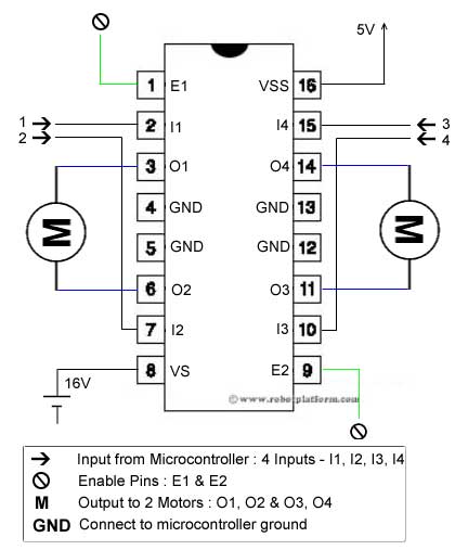
- Pin8 powers the two motors and should be connected to
positive lead of a secondary battery. As per the datasheet, supply voltage
can be as high as 36 Volts.
3.6 Light Emitting Diode :
.svg)
Fig.3.9(a) Light Emitting Diode
A light-emitting diode (LED)
is a semiconductor
light source. LEDs are used as indicator lamps in many devices and are
increasingly used for other lighting.
Introduced as a practical electronic component in 1962, early LEDs emitted
low-intensity red light, but modern versions are available across the visible,
ultraviolet
and infrared
wavelengths, with very high brightness.
When a light-emitting
diode is forward biased (switched on), electrons
are able to recombine
with electron holes
within the device, releasing energy in the form of photons.
This effect is called electroluminescence
and the color
of the light (corresponding to the energy of the photon) is determined by the energy gap
of the semiconductor. An LED is often small in area (less than 1 mm2),
and integrated optical components may be used to shape its radiation pattern.
LEDs present many advantages
over incandescent light sources including lower energy consumption,
longer lifetime,
improved robustness, smaller size, faster switching, and greater durability and
reliability. LEDs powerful enough for room lighting are relatively expensive
and require more precise current and heat management
than compact fluorescent lamp
sources of comparable output.
Light-emitting diodes are used in
applications as diverse as replacements for aviation lighting, automotive lighting
(particularly brake lamps, turn signals and indicators) as well as in traffic
signals. The compact size, the possibility of narrow bandwidth, switching
speed, and extreme reliability of LEDs has allowed new text and video displays
and sensors to be developed, while their high switching rates are also useful
in advanced communications technology. Infrared LEDs are also used in the
remote control units of many commercial products including televisions, DVD
players, and other domestic appliances.
Lifetime and failure
Solid
state devices such as LEDs are subject to very limited wear and tear
if operated at low currents and at low temperatures. Many of the LEDs made in
the 1970s and 1980s are still in service today. Typical lifetimes quoted are
25,000 to 100,000 hours but heat and current settings can extend or shorten
this time significantly.
CHAPTER 4
FIRMWARE IMPLEMENTATION OF THE PROJECT DESIGN
Firmware
Implementation:
This
chapter briefly explains about the firmware implementation of the project. The
required software tools are discussed in section 4.2.
4.1 Software Tool
Required:
Arduino
1.0.6 software tools used to program microcontroller. The working of software
tool is explained below in detail.
4.1.1
Programming Microcontroller:
A compiler for a
high level language helps to reduce production time. To program the Arduino UNO
microcontroller the Arduino is used. The programming is done strictly in the
embedded C language. Arduino is a suite of executable, open source software development
tools for the microcontrollers hosted on the Windows platform.
Arduino is a tool
for making computers that can sense and control more of the physical world than
your desktop computer. It's an open-source physical computing platform based on
a simple microcontroller board, and a development environment for writing
software for the board.
One of the
difficulties of programming microcontrollers is the limited amount of resources
the programmer has to deal with. In personal computers resources such as RAM
and processing speed are basically limitless when compared to microcontrollers.
In contrast, the code on microcontrollers should be as low on resources as
possible
4.2.
About Arduino IDE:
4.2.1.
Get an Arduino board and USB cable
You also need a standard USB cable (A plug to B plug): the kind
you would connect to a USB printer, for example. (For the Arduino Nano, you'll
need an A to Mini-B cable instead.)


4.2.2.
Connect the board:
The Arduino Uno, Mega, Duemilanove and Arduino Nano automatically
draw power from either the USB connection to the computer or an external power
supply. If you're using an Arduino Diecimila, you'll need to make sure that the
board is configured to draw power from the USB connection. The power source is
selected with a jumper, a small piece of plastic that fits onto two of the
three pins between the USB and power jacks. Check that it's on the two pins
closest to the USB port. Connect the Arduino board to your computer using the
USB cable. The green power LED (labelled PWR) should go on.

Open the blink example
Open the LED blink example sketch: File > Examples >
1.Basics > Blink.

Fig:
OPENING BLINK EXAMPLE

Fig:
SOURCE CODE WRITTEN IN ARDUINO COMPILER
Select your board
You'll need to select the entry in the Tools >
Board menu that corresponds to your Arduino.

Fig: Selecting an Arduino Uno
4.2.3 Writing
Sketches:
Software written using Arduino are called sketches. These
sketches are written in the text editor. Sketches are saved with the file
extension .ino. It has features for cutting/pasting and for searching/replacing
text. The message area gives feedback while saving and exporting and also
displays errors. The console displays text output by the Arduino environment
including complete error messages and other information. The bottom righthand
corner of the window displays the current board and serial port. The toolbar
buttons allow you to verify and upload programs, create, open, and save
sketches, and open the serial monitor.
NOTE: Versions of the IDE prior to 1.0 saved sketches with the
extension .pde. It is possible to open these files with version 1.0, you will
be prompted to save the sketch with the .ino extension on save.
Verify
Checks your code for errors. |
|
|
Note:
If you are using an external programmer, you can hold down the
"shift" key on your computer when using this icon. The text will
change to "Upload using Programmer"
|
|
New
Creates a new sketch. |
|
Open
Presents a menu of all the sketches in your sketchbook. Clicking one will open it within the current window.
Note:
due to a bug in Java, this menu doesn't scroll; if you need to open a sketch
late in the list, use the File | Sketchbookmenu instead.
|
|
Save
Saves your sketch. |
|
Additional commands are found within the five
menus: File, Edit, Sketch, Tools, Help. The menus are
context sensitive which means only those items relevant to the work currently
being carried out are available.
4.2.4 Select
your serial port:
Select the serial device of the Arduino board from the Tools |
Serial Port menu. This is likely to be COM3 or higher
(COM1and COM2 are usually reserved for hardware serial ports). To
find out, you can disconnect your Arduino board and re-open the menu; the entry
that disappears should be the Arduino board. Reconnect the board and select
that serial port.
4.2.5 Upload
the program:
Before uploading your sketch, you need to select the correct items
from the Tools > Board and Tools > Serial Portmenus. The boards are
described below. On the Mac, the serial port is probably something like /dev/tty.usbmodem241 On Windows, it's
probably COM1 or COM2 (for a serial board)
or COM4, COM5, COM7, or higher (for a USB board) - to find out,
you look for USB serial device in the ports section of the Windows Device
Manager. On Linux, it should be /dev/ttyUSB0,/dev/ttyUSB1 or similar.
Once you've selected the correct serial port and board, press the
upload button in the toolbar or select the Upload item from the File menu. Current Arduino boards will reset automatically
and begin the upload. With older boards (pre-Diecimila) that lack auto-reset,
you'll need to press the reset button on the board just before starting the
upload. On most boards, you'll see the RX and TX LEDs blink as the
sketch is uploaded. The Arduino environment will display a message when the
upload is complete, or show an error.
When you upload a sketch, you're using the Arduino bootloader, a small program that has
been loaded on to the microcontroller on your board. It allows you to upload
code without using any additional hardware. The bootloader is active for a few
seconds when the board resets; then it starts whichever sketch was most
recently uploaded to the microcontroller. The bootloader will blink the
on-board (pin 13) LED when it starts (i.e. when the board resets).
Now, simply click the "Upload" button in the
environment. Wait a few seconds - you should see the RX and TX leds on the
board flashing. If the upload is successful, the message "Done
uploading." will appear in the status bar. (Note: If you have
an Arduino Mini, NG, or other board, you'll need to physically present the
reset button on the board immediately before pressing the upload button.)

Fig: COMPILATION UNDER PROCESS
A few seconds after the upload finishes, you should see the pin 13
(L) LED on the board start to blink (in orange). If it does, congratulations! You've
gotten Arduino up-and-running.
CHAPTER 5
FLOW CHART AND CIRCUIT
DIAGRAM
FLOW
CHART :

CIRCUIT
DIAGRAM :
SOURCE
CODE :
int ir1=4;
int ir2=5;
int ir3=6;
int ir4=7;
int red_led=12;
int green_led=11;
int buzzer=8;
int IN1=9;
int IN2=10;
int sensor1=0,sensor2=0,sensor3=0,sensor4=0;
int va1;
int va2;
int bstate1=0;
int count=0;
void setup()
{
pinMode(ir1,INPUT);
pinMode(ir2,INPUT);
pinMode(ir3,INPUT);
pinMode(ir4,INPUT);
pinMode(red_led,OUTPUT);
pinMode(green_led,OUTPUT);
pinMode(IN1,OUTPUT);
pinMode(IN2,OUTPUT);
pinMode(buzzer,OUTPUT);
digitalWrite(IN1,HIGH);
digitalWrite(IN2,HIGH);
digitalWrite(red_led,HIGH);
digitalWrite(green_led,HIGH);
digitalWrite(buzzer,HIGH);
}
void loop()
{
st:
digitalWrite(green_led,LOW);
digitalWrite(red_led,HIGH);
digitalWrite(buzzer,HIGH);
digitalWrite(IN1,HIGH);
digitalWrite(IN2,HIGH);
while(1)
{
/*
sensor1=digitalRead(ir1);
sensor2=digitalRead(ir2);
sensor3=digitalRead(ir3);
sensor4=digitalRead(ir4);
*/
if((digitalRead(ir1)==HIGH&&digitalRead(ir2)==HIGH)||(digitalRead(ir3)==HIGH&&digitalRead(ir4)==HIGH))
{
if(digitalRead(ir1)==HIGH&&digitalRead(ir2)==HIGH)
count=1;
else
count=2;
digitalWrite(buzzer,LOW);
digitalWrite(red_led,LOW);
digitalWrite(green_led,HIGH);
digitalWrite(IN1,LOW);
digitalWrite(IN2,HIGH);
delay(500);
digitalWrite(buzzer,HIGH);
delay(1000);
digitalWrite(IN1,HIGH);
digitalWrite(IN2,HIGH);
if(count==1)
while(digitalRead(ir3)==LOW&&digitalRead(ir4)==LOW);
else
while(digitalRead(ir1)==LOW&&digitalRead(ir2)==LOW);
digitalWrite(buzzer,LOW);
digitalWrite(red_led,LOW);
digitalWrite(green_led,HIGH);
digitalWrite(IN1,HIGH);
digitalWrite(IN2,LOW);
delay(500);
digitalWrite(buzzer,HIGH);
delay(1000);
digitalWrite(IN1,HIGH);
digitalWrite(IN2,HIGH);
goto st;
}
}
}
CHAPTER 8
CONCLUSIONS AND FUTURE SCOPE
CONCLUSIONS
:
Sensor based railway gate control
system is centered on the idea of reducing human involvement for closing and
opening the railway gate which allows and prevents cars and humans from
crossing railway tracks. The railway gate is a cause of many deaths and
accidents. Hence, automating the gate can bring about a ring of surety to
controlling the gates. Human may make errors or mistakes so automating this
process will reduce the chances of gate failures. Automation of the closing and
opening of the railway gate using the switch circuit reduces the accidents to a
greater extend. The obstacle detection system implemented reduces the accidents
which are usually caused when the railway line passes through the forest. Most
of the times greater loss has been caused when animals cross the tracks.
FUTURE SCOPE :
The limitation of this project is the
use of IR sensors. Hence, any obstacle in the way of the sensor will be
detected. Another important limitation is that this project does indeed close
and open the gate but it cannot control the crossing of cars and vehicles. It
only controls the gate. To combat this problem pressure sensors can be used as
extension to the work. We are using IR sensors but it is better to use load
sensors. We have not used load sensors because it was not economically feasible.
As a future scope of work, our system can be implemented in real time by fixing
the current limitations using new technologies.